
FictivMade: Designing a Multi-Tool Phone Stand — Part 1 🛠️
From first sketches to CAD and early prototypes—my process for building a pocket-sized tool with DFM in mind.

👋 I’m David Willson, a mechanical engineer with 10+ years in product development. In this series, I’m walking through the process of designing and prototyping a multi-tool phone stand—sharing the same decisions, trade-offs, and lessons I work through on real projects.
🎥 Check out the full video breakdown (for when you’d rather watch than read): Watch on YouTube
Why This Project
I wanted to design something that mechanical engineers would actually use day-to-day. The idea wasn’t to build a flashy gadget, but a practical tool you’d keep on your desk or throw in your pocket.
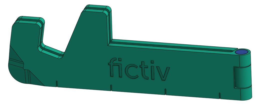
It also needed to double as a trade show giveaway and a way to demonstrate Fictiv’s injection molding capabilities. That meant the design had to walk a fine line: functional enough to be useful, small enough to hand out, and manufacturable enough to highlight DFM concepts.
Early Concept Work
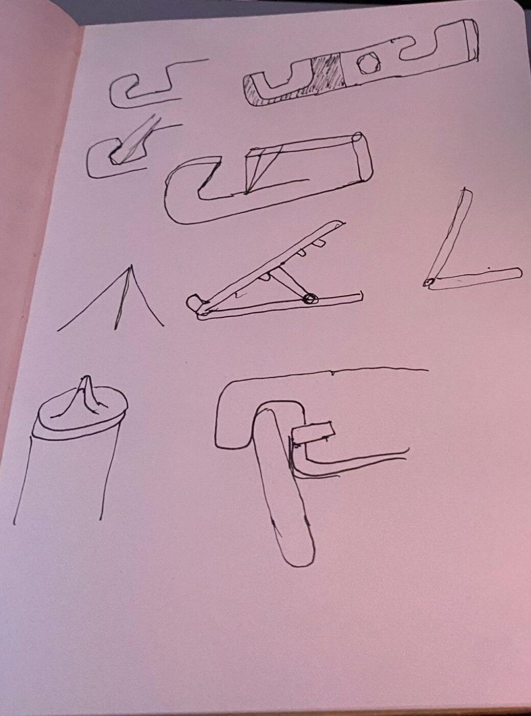
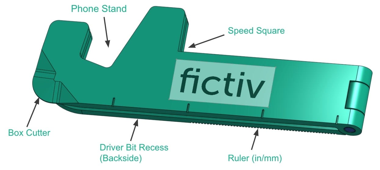
The first step was brainstorming. I looked at a few directions: a phone stand, a box cutter, a small multi-tool. Instead of picking one, I decided to combine features into a compact form factor.
I always start with sketches, even rough ones. They help me catch bad geometry decisions early, before I burn time in CAD. At this stage I was trying to balance aesthetics (clean, brand-worthy) with utility (box opener, phone slot, hinge).
CAD Modeling
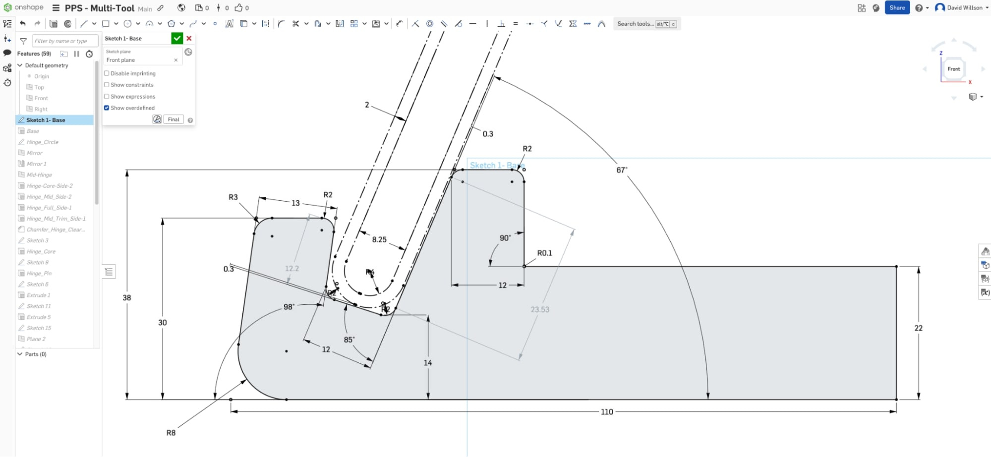
For CAD, I used Onshape and a top-down master modeling approach. I built everything off a single skeleton sketch — dimensions, hinge thickness, phone slot, etc. That way, changes cascade through the model without breaking features.
A couple of things I paid attention to:
Hinge design: The hinge pin diameter set the width in collapsed form. Tolerance stack-up had to be checked so the pin didn’t bind. I used our tolerance analysis calculator for this.
Symmetry: Mirroring around a mid-plane kept the design clean, but I delayed the mirror feature until late in the tree to avoid double-fixing errors.
Cutting edge: The box-cutter profile was modeled with a swept cut + chamfer, anticipating a metal insert for durability.
Prototyping
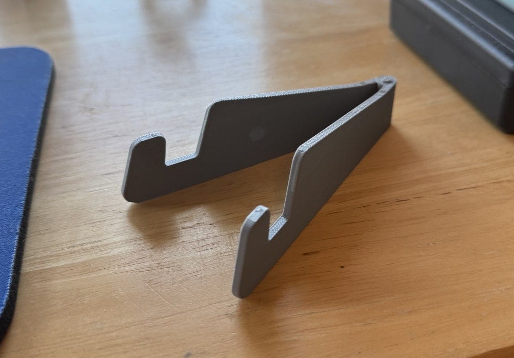
I ran quick prints on a Bambu Lab Carbon X1C to validate size, ergonomics, and the cutter edge. The prints were fine for form and fit, but the plastic edge obviously wasn’t strong enough. That confirmed the need for metal inserts for the sharp features and load-bearing spots (like a hex recess or bottle opener).
Fast iteration here mattered — print overnight, test in the morning, tweak in CAD the same day.
Manufacturing Considerations
Even at the concept stage, I kept DFM in mind:
Added draft on walls for injection molding.
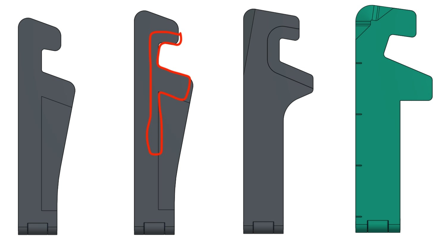
Eliminated undercuts around the hinge with fillets.
Left space for insert-molded metal features where strength was required.
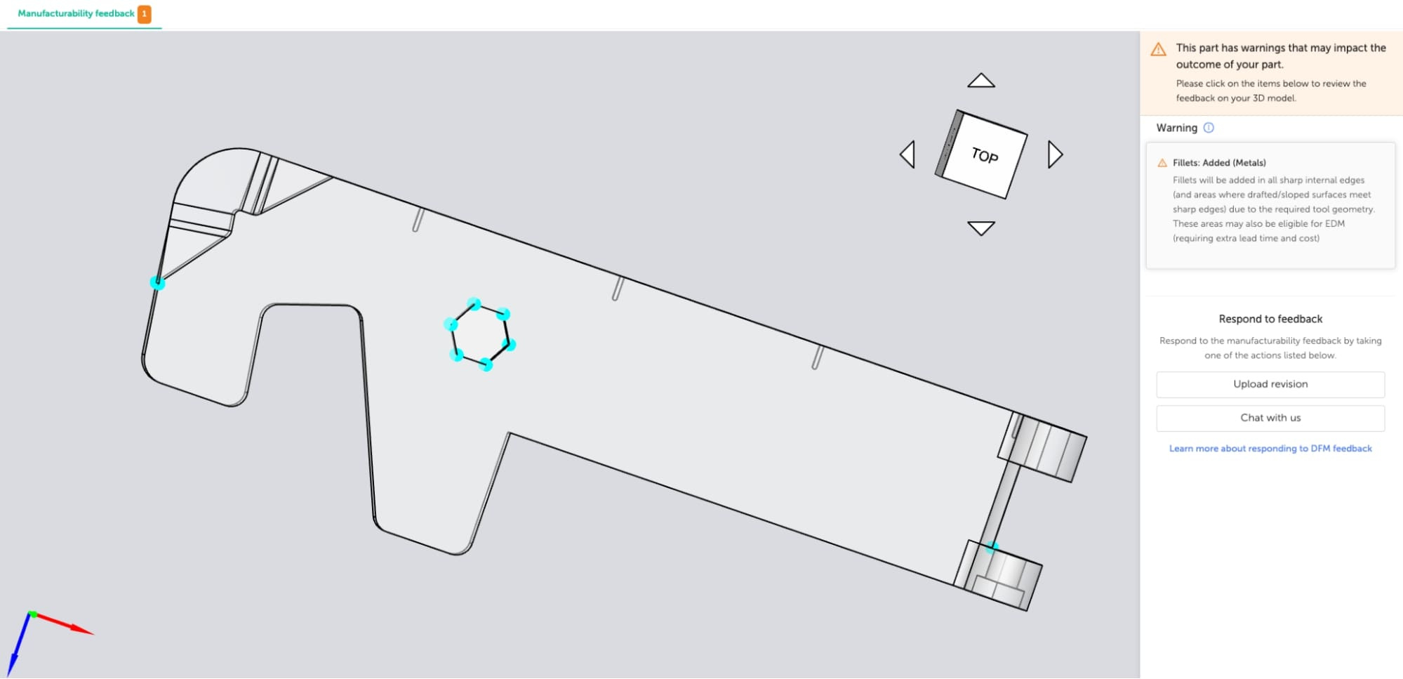
The Fictiv platform’s DFM feedback flagged issues like sharp internal corners right away, which is exactly the kind of feedback loop you want early.
Sharing the Design
I published the Onshape model so others can pull it apart, export .stl or .step, and run it through Fictiv for 3D printing or machining. If you want to adapt it to your own phone dimensions, you can — just note you’ll probably have to adjust hinge tolerances depending on process.
What’s Next
This is the first pass. Next up I’ll dive deeper into refining the design for production: material trade-offs, tolerance analysis, and how the prototype evolves into something you could actually scale.
⚡ Key lessons so far:
Sketch early, CAD smart.
Print often — nothing replaces a physical prototype.
Keep manufacturing in mind from the start.